

Introduction
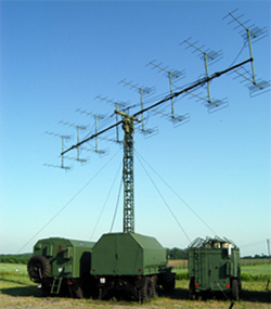
The P-18 radar modernization program started in 2000 and the HM Arzenál Co. handed over the first modernized radar to the Hungarian Army in 2002. Nowadays the modernized P-18 radar finds its place among the modern air surveillance systems of the Hungarian Army. It is a high-power, mobile, long-range radar that can be especially successfully applied for the reconnaissance of targets having small radar cross-section.
Main features of modernization
Due to the quality of signal processing (favourable rate of false plots) and the digital signal output the radar can be connected to modern air surveillance systems with digital inputs even in the case when the radar constitutes a part of mobile, deployed unit.
- Increasing the resolution from 2 km to 1 km
- Decreasing the error of range measurement from 1800 m to 1000 m.
- Decreasing the error of azimuth measurement
- Between 10 and 50 km from 1.5' to 1 ';
- Between 50 and 300 km from 1 ' to 0.8 '.
- Utilizing modern signal processing techniques increases the radar's clutter resistance and the capability to detect low radar cross-section targets
- Increasing stationary target suppression from 20dB to 40dB
- Many electron tube cabinets will be omitted and their functionality will be taken over by new units based on up-to-date parts, the reliability and availability of the radar will improve, and the adjustment and service demand will decrease at the same time.
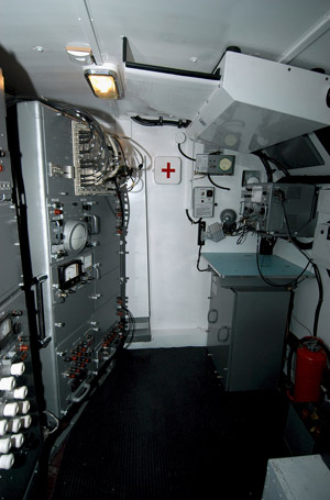
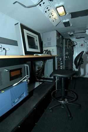
- Working conditions of the operators will be better, being in the possession of larger place in the air conditioned cabin. Moreover, the computer-based working place significantly helps and eases the operator's activities.
- Supporting the possibility of further development towards multistatic systems.
Remote CDU
Remote CDU:
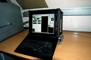
The remote controlling and displaying unit is a relatively small, portable computer that fulfils the tasks of the digital remote indicator. It connects via coaxial cable to the ARCNET router that can be found in the Receiving, signal processing and control unit. In case of need it can take over all the control functions and provide the continuous operation.
Objective control
The logged data can be replayed from a given time. By this the equipment realizes the full-scale objective control. The program provides an opportunity to select the recorded data. In this way they can be filtered by conditions given by the operator. By the help of this function a new, smaller database can be created that contains only the important data from the point of view of control.
Logging:
- Analog video pictur
- Synthetic radar information
- Error messages
- Operator's activities
Replaying:
- Logged data can be replayed from a given time
- Representation and filtering possibilities provided by the displaying subsystem operate during replaying, too
- Speed of replaying can be changed (1/8-16x).
Taking snapshots:
- The snapshot does not store the actual picture as a photograph, but records the data of the given air situation
- After loading the snapshot there is the possibility to change the centre and the zoom factor, moreover, the appearing information can be filtered at will, as in normal operation
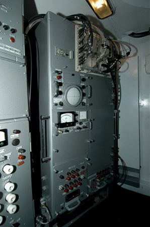
Units omitted during modernization
- Cabinet No. 1 (IKO)
- Cabinet No. 2
- Cabinet No. 6 (VIKO)
- Receiving unit No. 5
- Horizontal sweeping unit No. 7
- Vertical sweeping unit No. 8
- Indicator unit No. 10
- Calibrator unit No. 18
- Coupler unit No. 20
- Video signal mixer unit No. 25
- Amplifying unit No. 27
- Controlling indicator unit No. 56
- Potential scope unit No. 75
- Coherent oscillator unit No. 76
New units built-in during modernization
- Receiving, signal processing and control unit No. 100
- Azimuth and elevation converter unit No. 110
- ARCNET router unit No. 120
- AFC unit No. 140
- Trigger generator unit No. 150
- Control unit No. 170.
- High frequency receiving unit No. 190.
- Receiving and signal processing unit No. 200
- Controlling and displaying unit No. 600
- Remote control computer No. 690
- Analogue indicator interface unit No. 930
Receiving and signal processing unit
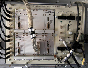
The modernized receiving and signal processing unit of the P-18 radar provides the amplification and mixing of the received low-level signal, and the adjustment of the bandwidth, too. The unit can be found in cabinet No. 3. The tube- and semiconductor construction has been replaced with a signal processor-based receiver.
The local oscillator has been replaced by an electronically tuned and moving parts free one. The receiver is fully digital-structured from the intermediate-frequency stages. Every receiver operation mode is implemented in pure software way, therefore the equipment needs less adjustment and maintenance. Signals arrive to the operator's workplace through onboard computer network.
Receiver operation modes can be set in software way, hence we have replaced the cable systems and switch signals having many error-possibilities with a digital control system. Every new unit continuously evaluates the received signals during operation, and if detects some anomaly it gives a warning.
The functions of the receiving and signal processing unit:
- Amplification, mixing and bandwidth adjustment of received low-level signal
- Realization of synthezer frequency tuning without moving parts
- Realization of clutter filtering possibilities (IF filter, asynchronous noise/clutter-filter, moving target indication, CFAR, VARU, plot filter)
- Providing different, pre-defined, optimized operation modes (amplitude, normalized amplitude, normalized amplitude with integration, MTI, normalized MTI, normalized MTI with integration)
- Realization of plot extractor functions with such a special plot forming, which supports the algorithm realizing the tracker's
- VHF correctionTransmission of digitalized analogue video picture and plots through network towards the controlling and displaying unit
The remote control of the functions of receiving and signal processing unit is realized fully via local network interface.
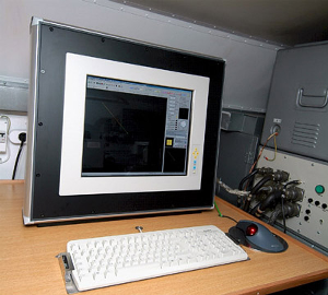
Controlling and Displaying Unit (CDU)
The function of the Controlling and Displaying Unit is to establish the man-machine interface between the operator and the radar. This unit allows the radar's switching on and off, selection of different operation modes, adjustment of the different units of the radar, and displays on a uniform surface the analogue and synthetic air picture, moreover it provides the objective control functions, too.
The computer-based equipment can be easily handled and is clear-cut. On its displaying surface (Figure 6) appears the total air picture and the operator can get an overall picture about the radar operation.
The functions of CDU:
- Realizes man-machine interface.
- Provides the full-scale control of the radar.
- Creates track, which is at the same time the highest-level filtering carried out on the incoming plots.
- Displays the analogue indicator picture (25-30 frame/s, continuous, OpenGL based drawing, afterglow, time line).
- Displays the synthetic radar information (plots and tracks).
- Displays the static information (state borders, rivers, lakes, scale-signs, etc.).
- On a serial port it transmits the information requested by the Higher Echelon.
- Continuously receives the status data from the different radar units, evaluates them and informs the operator about their condition.
- Provides "A" type indicator for analyzing the analogue video signals.
- Realizes the objective control.
Filters and working modes
The operator may switch on the different filters separately or at the same time in order to clear the raw analogue picture from different noises and clutters. These filters are: IF filter, asynchronous clutter filter, moving target indication (MTI), CFAR, VARU and plot filter.
During operation the operator can select from different pre-defined operation modes such as amplitude, normalized amplitude, normalized amplitude with integration, MTI, normalized MTI, normalized MTI with integration.
The equipment includes a tracker which - taking into account the technical parameters of the radars and the kinetic characteristics of the flying objects - arranges the incoming plots into tracks. As a result of it the targets detected by the radar appear for the operator, displaying their speed and heading.
The tracker contains a VHF correction algorithm that can correct VHF radars' specific error of the echo signal splits or only a part of it appears in some antenna rotations.
DU displaying possibilities:
- Displaying the analogue indicator picture. In case of zooming the resolution is automatically increased
- Displaying the synthetic radar information (primary plot and track)
- Possibility for switching and rotation of track labels
- Displaying the static information (state borders, rivers, lakes, scale-signs, limits of digital signal processing, etc.)
- Possibility for modification of the zoom factor, and the possibility for changing the representation centre
- Possibilities for direction- and distance measurement
- Colour and symbol set which can be defined by the user
Supporting the error detection
By the continuous transmission of status information the program sends information for the operator about the condition of the radar units, supporting to a great extent the error detection and trouble shooting, if necessary.
Receiving and displaying of status data:
- AFC unit
- Analog indicator interface
- ARCNET router
- Azimuth and elevation converter
- Receiving and signal processing unit
- Control unit
The operator's activity is supported by displaying the condition of units and subsystems by flash signals. The program also gives textual information about the status of whole system.