

Introduction
The P-37 radar modernization program started in 1997 and the HM Arzenál Co. handed over the first modernized radar to the Hungarian Army in 1999.
In the Hungarian Army the fulfilment of the air surveillance tasks are based on these modernized P-37 radars taking part in the creation of the uniform European air space situation.
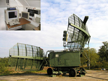
P-37
Main features of modernization
- Preparation for toleration of increased load (24 hours operation), among different weather conditions.
- Increasing the radar's reliability and building in advanced fault diagnostics functions
- Connection with digital signal processing and signal coupling to the modern, central air surveillance systems, even in
the case when the radar is a mobile, deployed unit. - Realization of limited height-finding capability using the digital signal processing of five receiving channels.
- Integration of secondary radar.
- Realization of analogue and synthetic radar signals integrated on a uniform displaying surface.
- Replacement of many electron tube cabinets and units by new units based on up-to-date parts, by which the reliability
and availability of the radar can be improved, and the adjustment and service demand will decrease at the same time. - Improvement of the working conditions of the operators, by creation of a more spacious air conditioned instrument cabinet, where a computer-based working place significantly helps and eases the operator's activities.
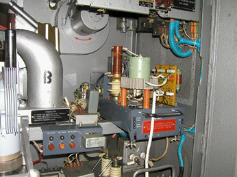
Transmitter system
The transmitter system of the P-37 is magnetron-based. After the modernization the basic principle has still remained, but we replaced the magnetron and thyratron units by new types with longer lifetime and more stable operation. The spectrum of the emitted signal of the transmitter has become clearer, and the operation safety of the equipment has significantly increased.
- Replacement of MI-29 magnetrons with type MI-503
- Replacement of the whole thyratron block
- Modification of transmitter protection system
- Modification of internal cable system
Features:
- Fivefold lifetime
- Clearer transmitter spectrum
- More balanced continuous operation
- Operation possible with MI-29 magnetron, too
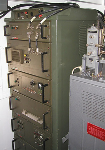
P-37 Transmitter system
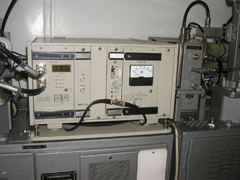
Receiving and signal processing system
Replacement of the receiving and signal processing unit of the radar has brought a change of many generations.The old structure with tubes and discrete-semiconductors has been replaced with a digital signal processor-based receiver.
The radar is fully digital from the IF stages.
The performed modifications:
- Replacement of the electronic and mechanic elements of
the whole receiving and signal processing unit - IF signal amplifying channel
- AFC IF channel
- Local oscillator and AFC system
- I-Q system coherent processing
- Amplitude operation mode
- Mixed operation modes
- Moving target indication (MTI)
- CFAR
- Supporting the height-finding
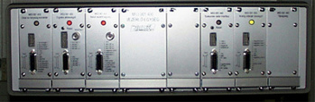
P-37 Receiving and signal processing system
Features:
- IF stage sampling (14 bits, 50MS/s)
- The second mixing and the forming of the I-Q channels are carried out digitally, with counter-type
oscillator and multiplier-type mixer. - Digital filter for IF bandwidth setting
- "Software receiver", the realization of every further receiving function is carried out with signal-processing processor
- Analogue and digital-coded analogue channel outputs
- Plot extractor
- ARCNET network communication
- Continuous operation checking
High frequency pre-amplifier
High frequency pre-amplifier stage built with travelling wave oscillator has been replaced with a fully semiconductor preamplifier, so its lifetime increased and is not susceptible to ageing. It provides the specified sensitivity throughout its whole lifetime.
Instead of different constant-frequency units per channels, identical wide band preamplifiers have been built in.
The performed modifications:
- Replacement of the whole high-frequency pre-amplifier.
- Increased protection against the signals of the own transmitter system.
- Modification of the cable system.
Features:
- Fully semiconductor design.
- Minimal -86 dB sensitivity in every band (typically -87-89 dB).
- Interchangeability regarding the five channels.
- Compatibility with the non-modernized P-37 radars.
Objective control
The logged data can be replayed from a given time. By this the equipment realizes the full-scale objective control. The program provides an opportunity to select the recorded data. In this way they can be filtered by conditions given by the operator. By the help of this function a new, smaller database can be created that contains only the important data from the point of view of control.
Logging:
- Analog video picture
- Synthetic radar information
- Error messages
- Operator's activities
Replaying:
- Logged data can be replayed from a given time
- Representation and filtering possibilities provided by the displaying subsystem operate during replaying, too
- Speed of replaying can be changed (1/8-16x).
Taking snapshots:
- The snapshot does not store the actual picture as a photograph, but records the data of the given air situation
- After loading the snapshot there is the possibility to change the centre and the zoom factor, moreover, the appearing information can be filtered at will, as in normal operation
Local oscillator
The structure of the local oscillators is electronically tuned and moving parts free.
The performed modifications:
- Realization of high-frequency basic signal.
- Step raster of 25 or 50 kHz.
- AFC function.
- Real IF frequency checking and displaying.
- High frequency stability and favourable phase noise.
- Amplitude amplifying onto a level suitable for the mixers.
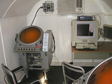
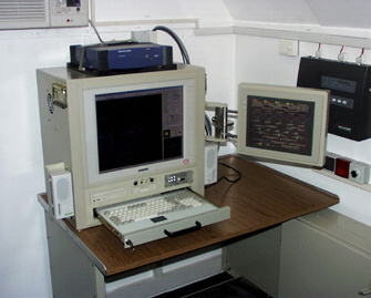
Controlling and Displaying Unit (CDU)
The Controlling and Displaying Unit is installed in the instrument cabin. The signals get to the operator's workplace via computer networks. In order to check the digital signals, they are retransformed for the PP indicators.
The duty of the CDU is to establish the man-machine interface between the operator and radar. This unit allows the radar's switching on and off, selection of different operation modes, adjustment of the different units of the radar, and displays on a uniform surface the analogue and synthetic air picture, moreover it provides the objective control functions, too.
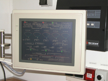
Controlling and Displaying Unit
Controlling and Displaying Unit
Modifications carried out in the instrument cabin:
- CDU (digital indicator)
- Analogue indicator picture displaying
- Synthetic radar picture (primary, secondary plots)
- Taking over the remote control functions
- IBM compatible personal computer with 18" TFT monitor
- RS422 data output interface with primary and secondary plot channels for data transmission - Application of two pieces PP indicators with digital interfaces for analogue picture displaying
- New, remote control computer (notebook)
- Local network installation
- New power-current distribution box
- Air conditioning system
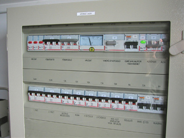
Power-current distribution box
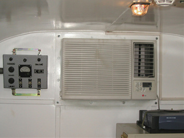
Air conditioning system
The CDU is a personal computer-based equipment, which - for the sake of a good handling and being clear-cut - has two displaying surfaces. The total air picture appears on the basic surface and the operator can get an overall picture about radar operation. This surface provides the adjustment of radar units and different displaying methods, furthermore it gives detailed information about the condition of radar units.
Every function is available on the basic surface, but in order to continuously watch the radar information the operator performs the radar control and the selection of the different operation modes on the auxiliary touch-screen terminal.
General features of CDU: / Controlling and Displaying Unit (CDU)
- Realizes man-machine interface.
- Displays the analogue indicator picture.
- Displays the synthetic radar information
- On a serial port it distributes the plot data for the HE (Higher Echelon).
- It continuously receives the status data from different radar units, evaluates them and informs the operator about their condition.
- In order to realize the objective control the logging is continuous, which allows the replaying of the recorded data,
and the operator can take photos as well.
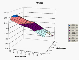
Determinants of height-finding
The four lower receiver channels play the most important role, therefore all of them must operate. Otherwise - in certain domains - the error increases. Height-finding accuracy increases with more receivers detecting the same target. The program makes it possible to enter the domain of height-finding, then it calculates the optimal elevation of lower and upper antennas and the average beam overlap can be reached in this way.
Height finding works under the best conditions when the beam overlap is as high as possible.
Control possibilities / Controlling and Displaying Unit (CDU)
Transmitter system:
- Switching on and off the transmitters
- Displaying the magnetron currents, protection of transmitters
- Displaying the status and error messages
- Selection among different trigger modes
- Activation and adjustment of counter-measure against homing missiles
- Providing the selection of polarization in the three lower channels
Rotary system:
- Starting and stopping the rotation
- Displaying the actual revolutions per minute
- Adjustment and displaying of the elevation of lower and upper antennas
Receiver system:
- Switching on and off the receivers
- Adjustment of the common and individual receiver amplifications
- Noise level adjustment (in case of CFAR)
- Adjustment of coherent receipt limit
- Adjustment of plot extractor threshold
- Switching on and off the different receiving operation modes (filters)
- Switching on and off the Siemens 1990
- Adjustment of different interrogation modes
- Activation of different testing and checking possibilities
- Displaying the status and error messages of the equipment
Displaying possibilities / CDU
- Horizontal or vertical displaying mode
- Unified displaying surface
- Displaying the analogue indicator picture, in case of zooming the resolution is automatically increased
- Displaying the synthetic radar information (primary or secondary plot, secondary track)
- Displaying the static information (state borders, rivers, lakes, scale-signs, limits of digital signal processing, etc.)
- Filtering possibility in accordance with the information source (primary or secondary)
- Filtering possibility in accordance with the altitude
- Possibility for switching and rotation of secondary track labels
- Possibility for modification of the zoom factor, and the possibility for changing the representation center
- Possibilities for direction- and distance measurement
- Colour and symbol set which can be defined by the user
Supporting the error detection
By the continuous transmission of status information the program sends information for the operator about the condition of the radar units, supporting to a great extent the error detection and trouble shooting, if necessary.
Receiving and displaying of status data:- Analogue video signal additive mixer
- Analogue indicator interface
- ARCNET router and summarizer
- Azimuth and elevation converter
- Receiving and signal processing units
- Secondary radar interface
The operator's activity is supported by displaying the condition of units and subsystems by flash signals. The program also gives textual information about the status of whole system.
Control system
The adjustment of the receiver operation modes can be carried out in a software way. For this purpose we have replaced the cable systems and switch signals having many error-possibilities with a digital control system.
The number of the rotating joint signals has decreased. It performs the control of the transmitter system, the tasks of rotation, trigger signal generation, azimuth and elevation system, and includes secondary radar extractor.
Control system
The performed modifications:
- Matching the heavy-current control system of the transmitter-receiver cabinet to the new system
- Omitting the ą27 V switching signals of rotating joint
- Simplification of cabin cable system
- Safety logic built together with fire alarm system for unattended heating of the cabin in winter
- Collecting and transmitting of checking signals
- Trigger signal generation by internal or external synchronization
- Azimuth and elevation data digitalization by keeping the original selsynes
- Sequential rotating system control
- Additive mixing the analogue signals of the five receivers
- Secondary radar extractor
- ARCNET network management